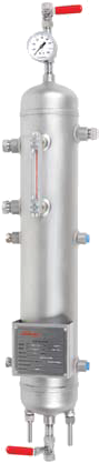
Buffer/Barrier Fluid Reservoir
ASME (ANSI) Duty
- Pressures up to 11 bar (160 psi)
- Temperature up to 65°C (150°F)
- Volume 11.4 liter (3 gallon)
- Meets the design criteria Section VIII, ASME B31.3, PED
- Plan 52 and 53A configurations
- Economical light duty reservoir for general service applications
- Instrumentation on each reservoir is according to local standards and can be adapted to suit application and customer requirements
- 304 and 316 stainless steel construction
- Connections are 0.500 inch or 0.750 inch NPT
- Cooling coil is optional
- Industry standard material certification available for components
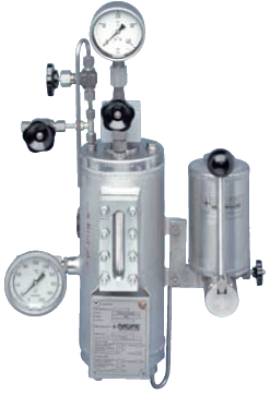
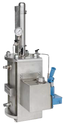
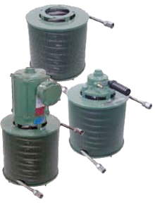
Buffer/Barrier Fluid Reservoir
ISO Duty
- Pressures up to 32 bar (464 psi) on 3 liter (0.8 gallon) and 6 liter (1.6 gallon), 20 bar (290 psi) on 10 liter
- Satisfies TRD design code requirements
- Plan 52 and 53A configurations
- Instrumentation on each reservoir is to German standards and can be adapted to suit application and customer requirements
- Connections are G 0.500
- Optional hand pump refills reservoir under pressure
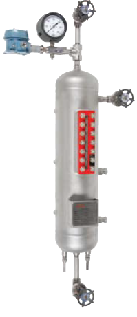
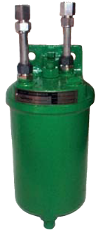
Buffer/Barrier Fluid Reservoir
API Duty
- Pressures up to 82.3 bar (1200 psi)
- Temperature up to 148°C (300°F)
- Volume 20 liter (5 gallon)
- Meets the design criteria of API 682, ASME Section VIII, ASME B31.3, PED
- Plan 52 and 53A configurations
- Construction: Threaded, socket welded, or butt welded
A wide range of instrumentation can be selected according to local standards and can be adapted to suit application and customer requirements
- 316/316L stainless steel construction
- Connections are 0.750 inch NPT or flange
- Optional cleanable cooling coil
- Industry standard material certification available for components
- Other design codes are available on request
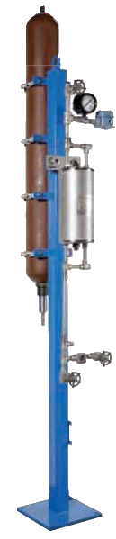
Barrier System
Plan 53B
- Pressures up to 82.3 bar (1200 psi)
- Temperature up to 148°C (300°F)
- Volume from 20 liter (5 gallon) up to 50 liter (13 gallon)
- Design contains either finned pipe air
cooling, a forced draft air cooling, or a
water cooler to dissipate seal or pump
heat
- Meets the design criteria of API 682,
ASME Section VIII, ASME B31.3, PED
- Threaded, socket welded, or butt welded
piping
- Carbon steel and 316 / 316L stainless
steel construction
- A wide range of instrumentation can be
selected according to local standards
and adapted to suit application and
customer requirements
- Each seal can be individually monitored
- Various accumulator sizes available to
satisfy various operating conditions
Piston Transmitter
Plan 53C
- Pressures up to 75.8 bar (1100 psi)
- Temperature up to 148°C (300°F)
- Volume up to 11.4 liter (3 gallon)
- A piston transmitter is a pressure
multiplier that generates barrier
pressure for dual pressurized liquid
seals based on the product pressure
- Used where the pressure in the pump
fluctuates or the inboard seal pressure
differential must be limited
- Pressure multiplier options:
1:1.1, 1:1.15, and 1:1.2
- Best used for pressures above
3.5 bar (50 psi)
- Can be provided with a cooling coil,
external heat exchanger,
instrumentation, and refill pump
- Standards: ASME or PED
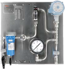
Buffer/Barrier Gas Panel
Plan 72, Plan 74
- Pressure up to 34.4 bar (500 psi)
- Temperature up to 93°C (200°F)
- Flow up to 14.2 lpm (30 SCFH)
- Buffer/Barrier gas panels combine flow
monitoring and control elements in a
self-contained, easy to use unit
- Used for unpressurized and pressurized
Flowserve gas seals
- Buffer panels provide unpressurized
dual seals with a gaseous quench to
flush inner seal leakage to a collection
system
- Barrier panels provide dual seals with
gaseous barrier pressure set higher
than the process pressure. This results
in a small amount of gas leakage into
the process and zero process leaking to
atmosphere
- Meets the design criteria of API 682,
ASME B31.3, PED
- Offers other configurations of
control systems ranging from simple
standard to complex custom designs
682 Seal Cooler
API 682
- Cooling coil 275 bar at 371°C (4000 psi at 700°F), 300 series stainless steel, Alloy 400, duplex 2205
- Cooling area 0.51 m2 (5.5 ft2)
- Shell 13.8 bar at 93°C (200 psi at 200°F), 300 series stainless steel
- High pressure seal coolers designed
in full compliance with API 682
- Fully vent and drain both product and
coolant sides
- Easy disassembly for cleaning without
damaging coils
- Standard materials are 300 series
stainless steel coil and shell for
superior corrosion resistance
- Process fluid flows through the coil
while coolant flows through the shell
- Can be provided with ASME U stamp
- Can be configured for series or
parallel flow
- Process fluid flows inside the coil,
coolant flows outside the coil
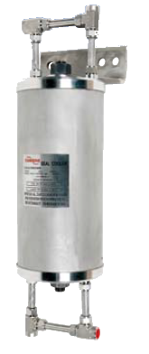
LD 682 Seal Cooler
API 682
- Cooling coil 193 bar at 371°C (2800 psi at 700°F), 316 stainless steel
- Cooling area 0.28 m2 (3.0 ft2)
- Shell 20.7 bar at 93°C (300 psi at 200°F), Carbon steel
- Economical seal coolers designed to meet the requirements of API 682
- Fully vent and drain both product and coolant sides
- Easy disassembly for cleaning without damaging coils
- Temperature indicator labels on shell surface measure cooling water temperature
- Process fluid flows through the coil while coolant flows through the shell
- European applications: according to 97/23/EC, PED - Pressure Equipment Directive, this equipment is covered by Article 3.3 (SEP - Sound Engineering
Practice)
- Option: a rupture disk prevents over-pressurization of cooling water side
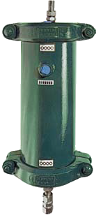
NX Seal Cooler
General Duty
- Cooling coil up 183 bar at 95°C (2650 psi at 200°F), 304 & 316 stainless steel, Alloy 400, Alloy 600
- Cooling area 0.16 to 0.54 m2 (1.75 to 5.80 ft2)
- Shell 10.3 bar at 93°C (153 psi at 200°F), Carbon steel, cast iron
- Light weight high pressure seal coolers for mechanical seal cooling
- Compact design is ideal for installation where space is limited - integral mounting foot and convenient pipe porting arrangement simplify installation
- Process fluid flows through the coil while coolant flows through the shell
- Easy access to tube coil for cleaning; shell and cover are fastened together with one bolt
Airfin Seal Cooler
Natural and Forced Draft
- Cooling coil up 141 bar at 95°C (2050 psi at 200°F), 304 stainless steel
- Cooling area 2.5 m2 (26.8 ft2)
- Air cooled seal coolers reduce temperatures surrounding the mechanical seal without using cooling water
- Airfin Seal Coolers offer substantial savings in flush water purchase and treatment, and they are less susceptible for fouling and require less piping
- Standard cooler types include 625 NC with natural convection and 625 FC with forced air using an electric or pneumatic motor
- Forced air cooler motors are explosion proof Class 1, Gr D, Div 1, 1/3 hp as standard
- Process fluid flows through the coil while air flows across the coil's finned exterior
- Fin materials include carbon steel, aluminum and stainless steel options
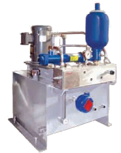
Circulator
Plan 54
- Flow 3.8 or 15 l/min (1 or 4 gpm)
- Pressure 27.6 bar (400 psi)
- Temperature 4.4 to -60°C (40 to 140°F)
- Volume 95 liter (25 gallon)
Features
- Plan 54 circulators are designed to provide clean barrier fluid at a controlled flow rate, pressure and temperature
- Flow is created by a positive displacement pump and pressure is controlled by valves
- System cleanliness is maintained using one or more high quality full flow liquid filters to ensure the fluid is clean and free of contamination
- Plan 54 systems can be instrumented to support multiple seals or pumps
- A wide range of instrumentation can be selected according to local standards and adapted to suit application and customer requirements
- Cooling coil inside the reservoir is optional
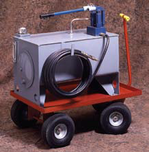
Filling Cart
Reservoir Refill
- Pressure 103 bar (1500 psi)
- Volume 76 liter (20 gallon)
- Refill your supply tanks in operation without pump downtime or venting unwanted gases to atmosphere
- Capable of injecting new barrier fluid into the supply tank at pressures up to 103 bar (1500 psi)
- Plan 54 circulators are designed to provide clean barrier fluid at a controlled flow rate, pressure and temperature
- Rugged construction, easy-tomaneuver 76 liter (20 gallon) reservoir with hand pump mounted on a cart with pneumatic tires
- Available with color-coded quick disconnects to prevent refilling with the incorrect barrier fluid